KaVo SUPERtorque 659 B Push Button XTend / Premium
KITS / TURBINES
Steel Turbine
907-1549
Ceramic Kit
907-3355
Ceramic Turbine
907-3349
ADDITIONAL PARTS
TOOLS
Blank Bur
907-1066
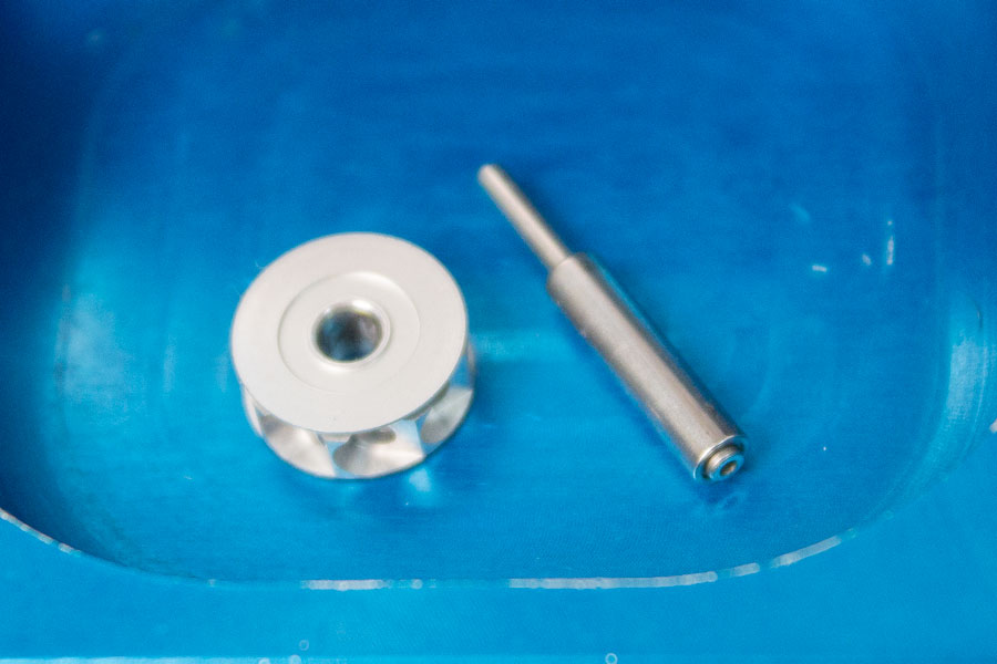
Impeller
HKV353
Autochuck
907-0199
Cap Wrench
107-5389
EZ Push Button Protector
907-1065
Insert B
907-1082
Insert C
907-1083
Insert 2
907-1074
BEFORE YOU BEGIN
After reviewing the training video and STEP-by-STEP instruction sheet, install the blank bur provided with your EZ Press. Tap the bur against the counter and try to pull it out using your fingers. If bur pulls out call ProScore for replacement spindle/collet.
STEP 1
Before starting if you have an OEM Cartridge STOP! You cannot repair this turbine. The rebuild kit is for ProScore turbines only.
Loosen head cap using appropriate cap wrench. Separate head cap and turbine. Remove and discard the 2 o-rings, and 2 loading springs.
Inspect the head and head cap for debris and clean thoroughly using a cotton swab and handpiece cleaner. If any debris is overlooked the turbine may not fit back into either the head cap or head and may bind.
Place Insert C under the spindle ram.
STEP 2
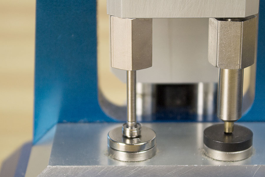
Locate one of the 3 holes below the ProScore Label on the EZ Press II. Loosen Insert #2 and place it over the top of the turbine. Press gently down on the turbine and turn the #2 Insert clockwise until you feel it just touch the chuck then turn the #2 Insert slightly counterclockwise. Place #2 Insert under bearing ram on the right.
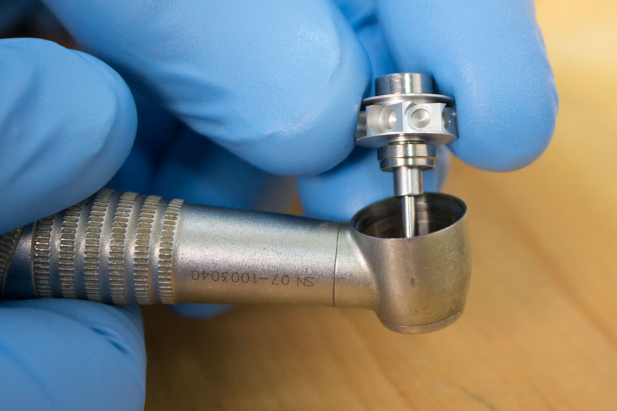
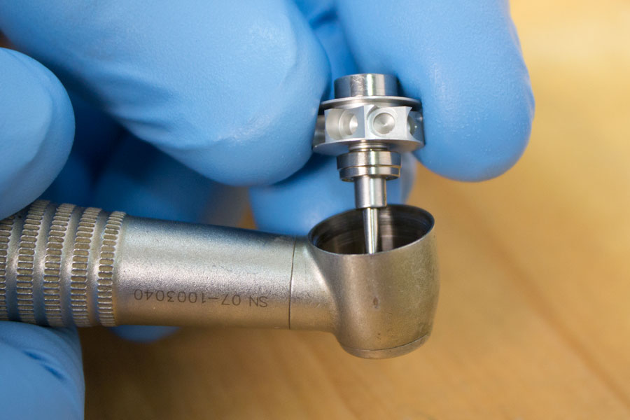
Place turbine in the center of insert C with the bur going down through the hole in the insert. Locate the EZ Push Button Protector that was included with your EZ Press. Feed the skinny end up into the spindle ram and hold in place. Slowly pull the handle down until the protector meets the rear of the spindle and covers the button. Verify all parts are aligned. Pull down on the handle firmly to push the rear bearing and impeller off of the spindle.
STEP 4
Remove Insert C and place Insert B underneath the Spindle Ram. Pick up the turbine and feed the blank bur up into the Spindle Ram. While holding the turbine in place slowly pull down on the handle until the spindle goes through the hole in Insert B and the front bearing is lying flat on the surface, then press the spindle out of the bearing.
STEP 5
Inspect the impeller for any damage. If any damage is detected order a replacement from ProScore. Place Insert #2 underneath the Bearing Ram.
STEP 6
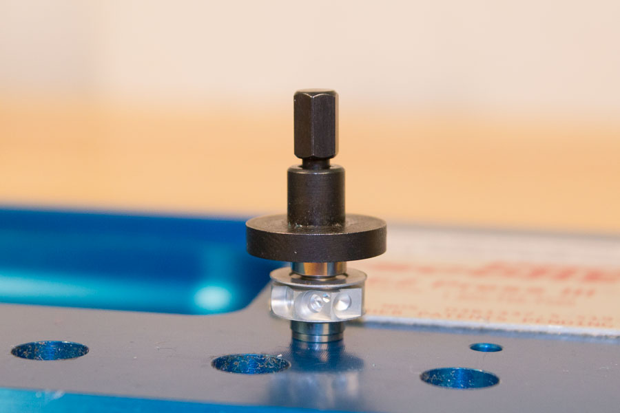
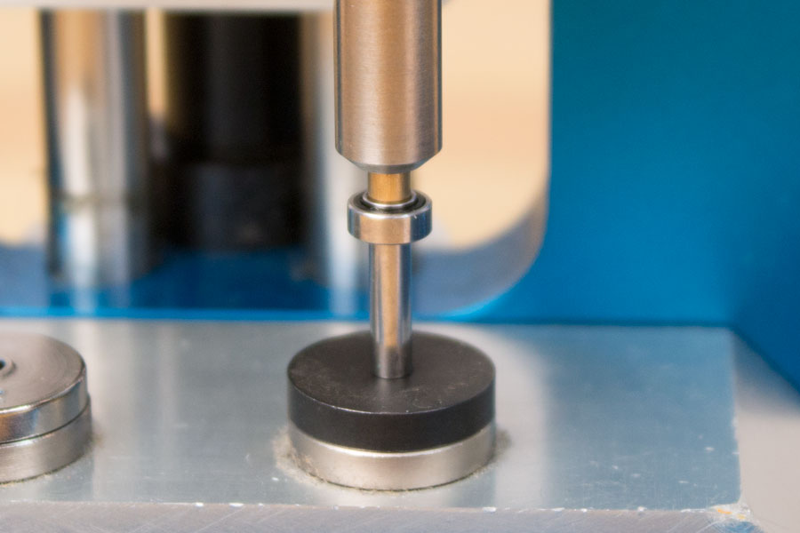
Open your rebuild kit and inspect the bearings. One bearing is stepped and one is smooth. Pick up the spindle and hold it so the bur points up. Drop the smooth bearing over the bur so the shielded or silver side of the bearing faces down, away from the bur and the black side faces up.
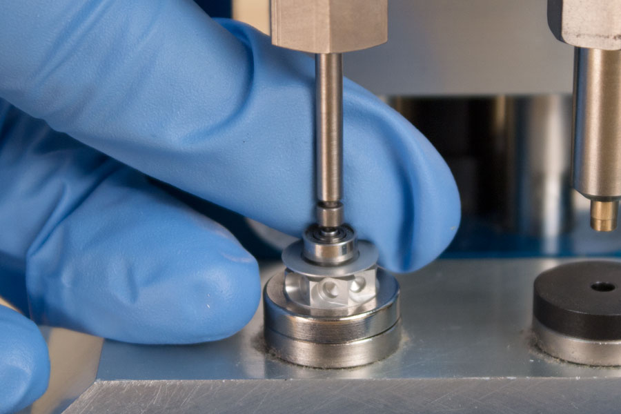
Once the bearing is in position feed the blank bur up into the bearing ram. Slowly pull down on the handle while holding the turbine in place until the rear of the spindle meets Insert #2. Gently press bearing down the spindle until it stops at Insert #2. If the bearing is riding loosely on the spindle use EZ Tight to hold it on
STEP 7
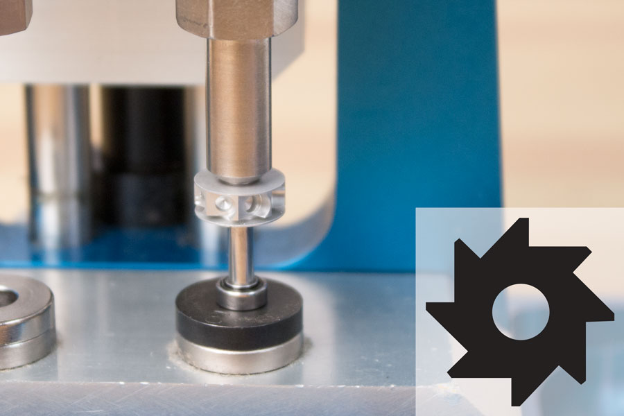
Hold the spindle so the bur points up and drop the impeller over the bur. Before pressing the impeller on check the direction. With the bur pointing directly away from you the blades at the 12 o’clock position should be slanting to the left.
Feed the bur up into the bearing ram on the right and hold in place. Slowly pull the handle down until the rear bearing meets Insert #2. Verify the end of the spindle is aligned with the hole in the center of Insert #2 then press down until it comes to a stop. If the impeller is riding loosely on the spindle order a replacement.
STEP 8
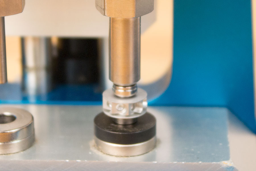
Locate the stepped bearing and drop it over the bur so the shielded or silver side is facing up towards the bur. Repeat pressing process until bearing comes to a stop when it reaches the impeller. If bearing is riding loosely on the spindle use EZ Tight to hold it on.
STEP 9
Place the bronze loading spring into the head of the heandpiece followed by one o-ring. Then place the silver loading spring followed by the last o-ring into the head cap. Seat the rear of the turbine into the head cap and install into the headpiece. Tighten cap down completely and make sure the bur rotates freely then test the performance. If the head cap heats up while testing stop and contact ProScore support.